4.1.1. Inserting elements
To draw an one-line network diagram in EA – PSM user should choose one of the icons from the Grid Elements pane (3 in
Main interface), each icon represents particular system element (see
4.2. Meanings of icons on the grid elements pane). When an icon is chosen, it is shown in a darker background, this means that now it is possible to add the element on a graphic window (4 in
Main interface) by clicking the left mouse button at any point of it. To deselect an icon just push Esc button on the keyboard. Elements like transformers and lines that need to be placed between two busbars are added in 3 simple steps:
-
Preferable element on the “Grid elements” pane is chosen.
-
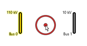
The first busbar is selected.
-
The second busbar is selected.
Another way to do this is to simply click on the white space between two busbars and element will be added automatically:
Parameters of the system element can be changed in its properties dialog which pops out after double-clicking on that element or after pushing the right mouse key on it and selecting “Properties”.
Hint: Ctrl + C will copy selected elements. CTRL + V will add copied elements to the scheme at the position of the mouse.
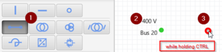
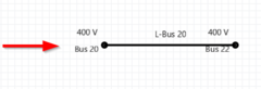
Hint: it is possible to draw a line without adding busbar first. User should select line element from the Grid Elements pane, hold CTRL button and left click on the desired start and end point of the line. After that, the line and busbars will appear:
Hint: If by any accident element was deleted or added not in the right place, user can always use “Undo” (Ctrl + Z) and “Redo” (Ctrl + Y) functions to correct a mistake.
Elements which need to be placed not between buses but onto the lines are added by these steps:
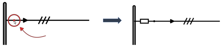
1. Choosing preferable element on the "Grid elements" pane.
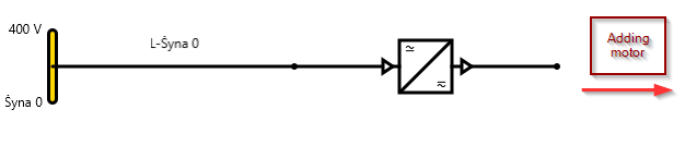
2. Clicking on the beginning or the end of the line, depending on where the element should be placed:
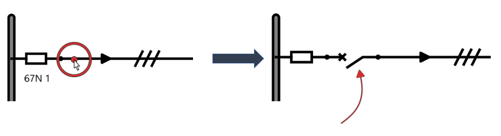
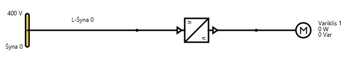
It is possible to add new element on the same line next to the existing element by clicking next to that element on prefered side:
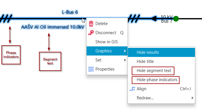
Hint: if power line is defined as a cable, phase indicators and segment text of cable type will apear next to the line. It is possible to hide it by right click on the line and selecting Graphics → Hide segment text / Hide phase indicators.
In this version of EA-PSM it is possible to build scheme by adding elements one by one. There is no need to place bus bars as in using EA-PSM 2018 release: