With EA-PSM user can model overload protection relays and use created models for further protection system development.
In order to create overload relay model, push “Modelling” button on the “Menu bar” and select “Standard overload Protections”. Siemens 3UA50 00-1K relay model will be created in this example. The relay technical data taken from the manufacturer’s publicly available sources is provided in the following table:
Setting range (A)
Times the setting current (x Ie)
1.2
3
4
5
6
7
8
8; 8.9; 10.1; 11.3; 12.5
7200
24.5
14.8
10.2
7.8
6.2
5.2
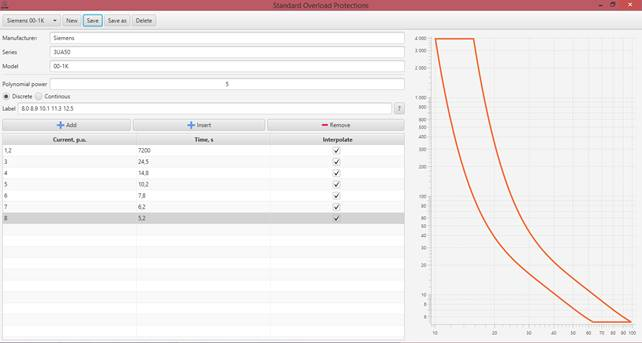
In the following picture relay modelling window is shown. The user can define “Manufacturer”, “Series” and “Model” titles. In “Label” window current settings should be defined. Between separate current settings values a space symbol must be left. In the list below, “Time, s” and “Current, p.u.” values should be defined from the manufacturer provided data.
Note: Current should be defined in a relative unit system, where the base value is the current setting (i.e. 8, 8.9, 10.1 and etc.)
When this data is provided, the user can “Save” model into the EA-PSM database. It is possible to add overload protection devices into the network from the elements panel, by selecting the protection in the breaker protections section.