20.7. Wires, cables, and towers modelling
In EA - PSM user can create templates for cables, overhead lines, and towers that can be used later for the one-line network diagram development. It is also possible to use EA-PSM built-in models of these network elements.
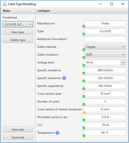
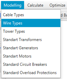
In order to create templates for previously mentioned elements, select “Modelling” from the main menu bar and choose “Wire types”, “Cable types” or “Tower types” from the drop down menu. The table will pop out in which user will have to enter the required parameters and press “Save” to save the model. To modify existing model, update its parameters and press “Save” button.
Note: The required parameters can be found from the specifications of the equipment, which is usually provided by the manufacturer.
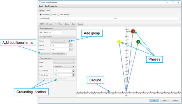
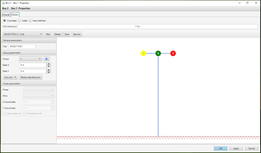
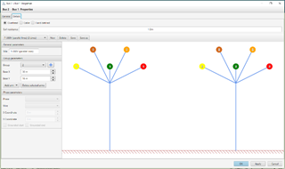
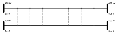
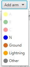
To create a custom tower type model, push “New” button enter its name. Phase coordinates are defined considering the base coordinate as the reference point. All group parameters are defined individually in “Group parameters” section by selecting the desired group from the list. Depending on the tower type, phase, neutral, grounding and lightning protection conductors can be added for each group separately by choosing the conductor type from the “Add arm” list.
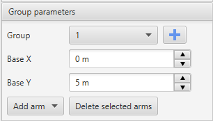
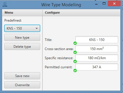
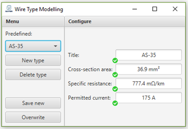
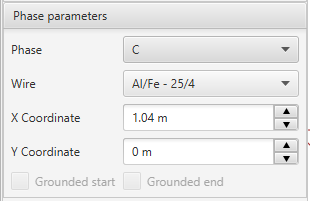
Each phase data is also defined separately. All phase coordinates are defined considering the base coordinates (“Base X” and “Base Y”) as the reference point. Base coordinate in EA-PSM represents the relative distance to the first tower and tower base height from the ground (first tower “Base X” should be set to 0). When setting each phase (arm) position it is convenient to select phase conductor (by pushing on it) in the tower drawing and define x and y coordinates (in meters) in “Phase parameters” section. Position can be also set by dragging phase symbols. Due to the sag of wire, the average height or 2/3 of the tower arms height should be entered. Each phase must have selected wire type from EA-PSM library (if desired wire is not in the library it can be defined manually by going to menu bar, selecting “Modelling → Wire Types”. In the opened window a new wire can be created by entering cross-section area, specific resistance and permitted current). If modeled phase is grounded, checkbox representing desired grounding location (start or end) should be checked.
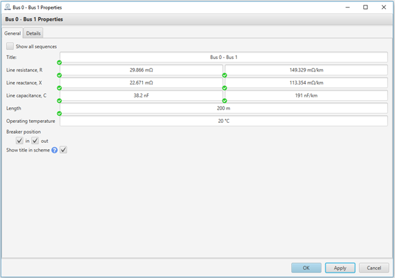
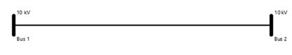
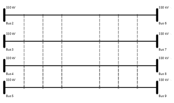
When the model is created, it can be applied to the desired lines by going to line properties, selecting “Overhead” option and selecting defined model from the list (note that tower type model does not have implied transmission line length and it should be defined individually to each line in the line properties “General” tab, “Length” field.
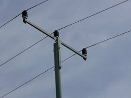
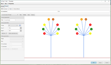
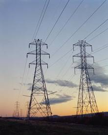
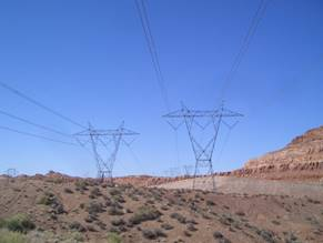
Some examples of created line tower types with EA-PSM:
The user can specify soil resistance for cable and overhead lines. It is used for one phase and two phases with ground connection short circuits calculation in grounded neutral systems.