Test cases are run before each EA-PSM version release. EA-PSM calculation results are compared to validation calculations. In this test case power flow calculations for Asymmetrical 3 phase network are performed. The difference in the results is less than 0.15% for all bus voltages, voltage drops, currents and power flows.
System description
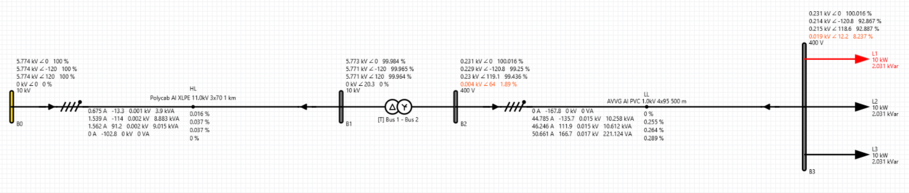
A low-voltage system with UN = 400 V and f = 50 Hz connected by a transformer to medium voltage grid. Network contains cable lines HL and LL, a transformer 10/0.4 kV and 3 loads connected on 3 phases. The elements impedances are described in Table 1.
Figure 1. Analyzed scheme
Table 1. Element parameters
Title
Voltage level
Resistance
Reactance
System “B0”
10 kV
170.03 mΩ
680.13 mΩ
Cable line “HL”
10 kV
500.151 mΩ
129 mΩ
Transformer “T”
0.4 kV
5.927 Ω
26.307 Ω
Cable line “LL”
0.4 kV
185.152 mΩ
38.75 mΩ
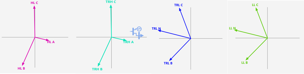
Picture 1. Phasor chart of voltages
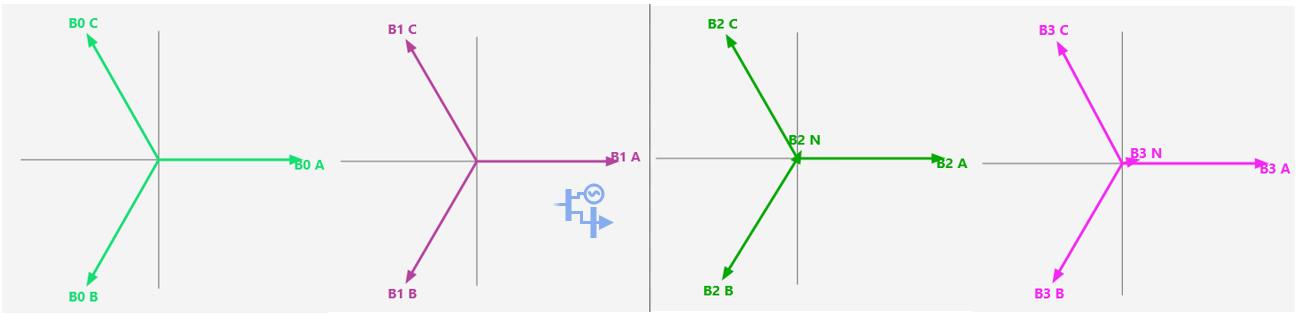
Picture 2. Phasor chart of currents
Calculation results
Asymmetrical current, voltage drop, power flow and power losses calculations were performed at cable line “LL”. Results of each calculation are depicted in Tables 2-5.
Currents in line “B2 – B3” can be calculated as follows:
Table 2. Currents flowing through cable line “LL”
Validation calculation
EA-PSM calculation
Calculation difference, %
Voltage drops in line “B2 – B3” can be calculated as follows:
Table 3. Voltage drops in cable line “LL”
Validation calculation
EA-PSM calculation
Calculation difference, %
Bus voltages at Bus 3 can be calculated as follows:
Power flows in line can be calculated as follows:
Table 4. Power flow in cable line “LL”
Validation calculation
EA-PSM calculation
Calculation difference, %
Power losses in line can be calculated as follows:
Table 5. Power losses in cable line “LL”
Validation calculation
EA-PSM calculation
Calculation difference, %
Power balance can be calculated as follows:
Power at busbar “B2” must be equal to power busbar “B0” minus the losses in cable line “HL” and in Transformer:
Table 6. Power balance calculation results
Value
Difference, %
Conclusions
Validation calculations based on Ohm’s law were performed to validate EA-PSM calculations. As it is seen most of the differences are within 0 – 0.1% range.