It is necessary to have one infinite bus in the system diagram before performing any of the calculations. Infinite bus represents the entire electrical network to which the analyzed system is connected. Therefore, the first bus added to the graphic window will be an infinite bus by default settings (infinite bus has a different color if compared to other buses) and the user will be asked to enter its parameters right after it is added.
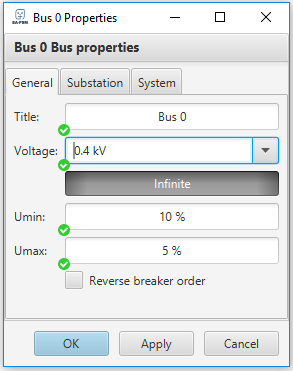
Firstly, the title and the voltage level of the infinite busbar should be entered in the “General” tab of the “Bus Properties” window. The user can leave the title which is assigned by default, however, it is necessary to enter the voltage level manually. Other parameters that can be changed in this tab is minimum voltage level and maximum voltage level . When calculating if the voltage level exceeds boundary conditions or busbar voltage rating will become red colored. Min and Max voltage levels for all busbars in the grid can be adjusted separately.
Furthermore, there might be cases when the breakers connected to the busbar need to be reversed by their order. For this case, there is a checkbox “Reverse breaker order”.
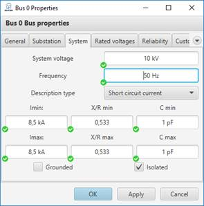
After first parameters are entered, the user shall define short circuit current in the “System” tab (short circuit power or system impedances can be entered instead, if known by choosing the appropriate description type from “Description type” menu). If the network is grounded, zero sequence impedances are also required. Furthermore, the capacitances Cmin and Cmax of the system network should be defined. These parameters are needed for both minimum and maximum system modes.
Hint: System parameters (short circuit power and etc.) are usually provided by a local power grid operator.
If the system is grounded, the user will be asked to specify zero sequence resistance and reactance, this data can be provided by a power grid operator. According to IEEE Recommended Practice for Grounding of Industrial and Commercial Power Systems, effective grounding is reached when zero-sequence reactance to positive-sequence reactance (X0/X1) is positive and less than 3, and the ratio of zero sequence resistance to positive-sequence reactance (R0/X1) is positive and less than 1.