In order to model an asymmetrical network, user should define asymmetrical elements. All asymmetrical elements (loads, inverters and other) should be defined the same way. For example, to define asymmetrical load, user should follow these steps:
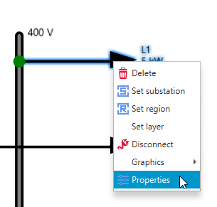
Insert a load to a desired place at the scheme and open its Properties by double clicking on it or with a right mouse click and selecting Properties:
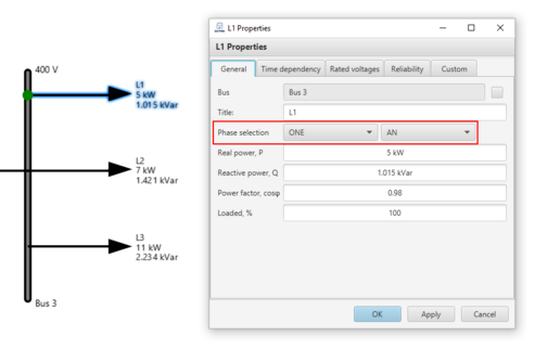
In the row Phase selection user can select ONE or TWO (depending on the asymmetrical load) and phase marking (A, B or C). If load is symmetrical, user should choose THREE.
Note: Cable properties must be defined according to the connection type of the upstream transformer. If the transformer has neutral cable must be compatable and also have neutral wire defined.
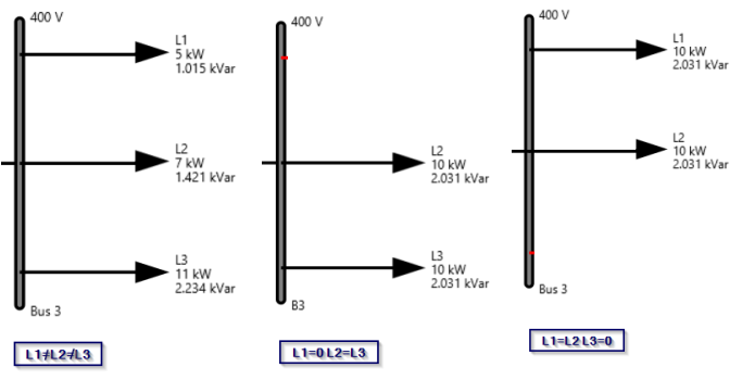
This way, user can model desired asymmetrical network, for example: