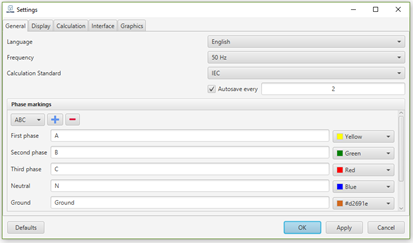
Settings window is reached through the Main menu bar selecting “Tools” → “Settings”. Here in tab “General” user could change program language, the frequency of AC, calculations standard, customize autosave options and select custom colours and names for phase markings.
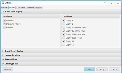
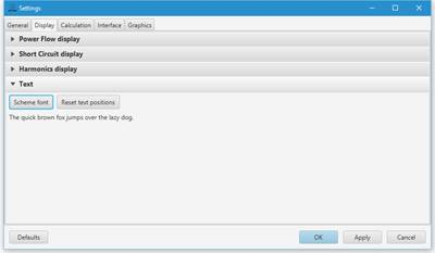
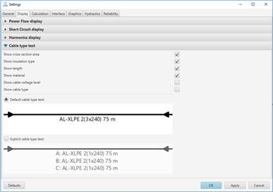
In tab “Display” it is possible to choose which of the calculated parameters should be displayed in an one-line diagram. In the Text section of the display options, the font can be selected. In the Cable Type Text section, the user can specify, which information about the cables should be displayed on the one line network diagram.
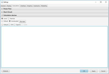
In tab “Calculation” the user can change power flow calculations accuracy and voltage factors for minimum and maximum short – circuit current calculations (check IEC 60909 for more details) and choose which calculation device to use. Currently it is possible to choose either Local calculation device (computer CPU or GPU) or Remote. For really challenging problems, Remote will allow to perform calculations using external processing unit instead of local one (for more details please contact “Energy Advice” team).
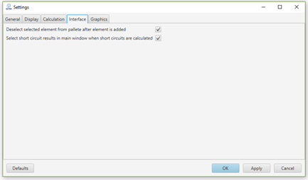
In tab “Interface” the user can turn on and off automatic element deselecting from elements panel, after adding it to the scheme (user can also find this button above elements panel, and short circuit result table actions after calculations are completed).
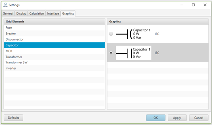
In tab “Graphics” the user can select which element graphic will be used in scheme drawing.
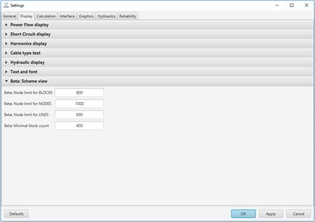
In order to improve visualization of big networks, for example, distribution network automatically imported from GIS, software allows to change “Scheme view” settings. These settings allow to efficiently work with big one-line network diagrams.